Constructing a Yagi-Uda Antenna: Step-by-Step Instructions
A Yagi-Uda antenna provides significant gain, allowing you to communicate over longer distances and improve signal clarity in ham radio communication. This guide offers detailed, easy-to-follow steps for building your own Yagi-Uda antenna, including crucial element spacing considerations. Whether you're a beginner or experienced ham, this project offers a rewarding learning experience.
Understanding the Yagi-Uda Antenna
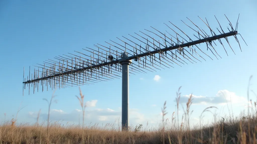
The Yagi-Uda antenna is a directional antenna, meaning it focuses its signal in one direction. It's comprised of three primary elements: the driven element (usually a dipole), the reflector, and one or more directors. The reflector is slightly longer than the driven element and is positioned behind it. The directors are shorter than the driven element and are positioned in front. The spacing and length of each element are critical to the antenna's performance.
Materials & Tools You'll Need
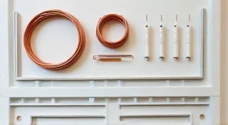
- Aluminum Tubing/Wire: (Approximately 1/2" diameter aluminum tubing works well, or use stiff wire like 12 AWG stranded wire. Calculate length based on frequency. See notes below.)
- Boom: (A strong boom is essential for stability. PVC pipe, wood, or fiberglass are common choices. Length depends on the number of elements.)
- Insulators: (To electrically isolate the elements from the boom.)
- Coaxial Cable: (RG-8X or RG-58, depending on your power requirements.)
- Connectors: (SO-239 or your preferred connector for the coaxial cable.)
- Measuring Tape:
- Saw: (For cutting the tubing/wire.)
- Drill: (For attaching insulators.)
- File/Sandpaper: (To smooth any sharp edges.)
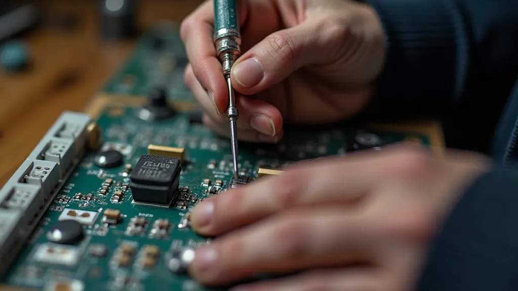
- Soldering Iron & Solder: (If using wire elements.)
Step-by-Step Construction
1. Planning and Calculations
Before you begin, you need to determine the frequency you're targeting. Different frequencies require different element lengths and spacing. Numerous online calculators are available to assist with these calculations. A common frequency is 146.52 MHz (2 meter band). Remember to plan the boom length to accommodate all elements.
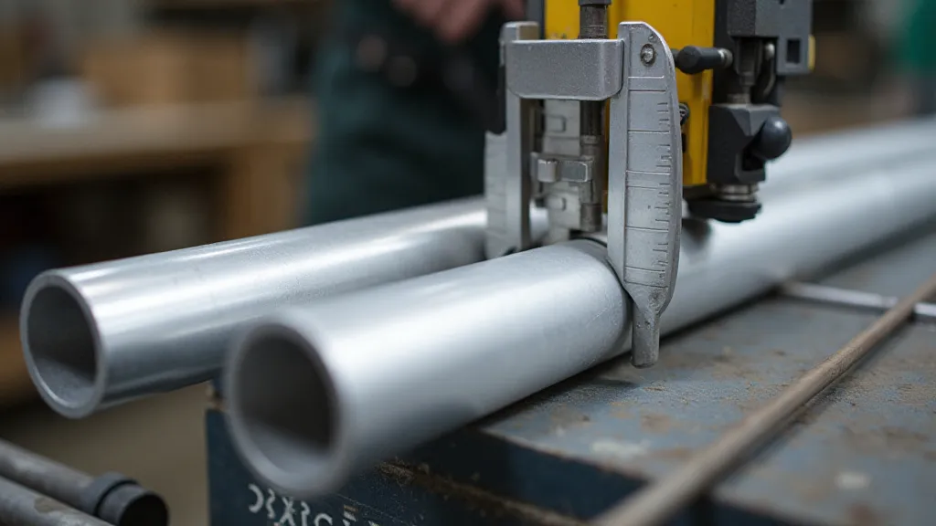
2. Cutting the Elements
Using your calculations, cut the aluminum tubing or wire to the precise lengths required for the reflector, driven element, and directors. Accuracy is crucial for optimal performance. Small variations can significantly impact gain and SWR. Don't rush this step.
3. Preparing the Boom
Cut the boom to the planned length. Drill holes for the insulators at the calculated positions for each element. Ensure the holes are appropriately sized for a secure fit. Use a file or sandpaper to remove any burrs or sharp edges around the drilled holes.
4. Attaching the Reflector
Attach the reflector element to the boom using insulators. The reflector should be positioned a calculated distance behind the driven element. Securely fasten the insulator to the boom and the reflector element. Ensure a clean electrical connection.
5. Installing the Driven Element
Attach the driven element to the boom, again using insulators. This element will be connected to the coaxial cable. Ensure a solid connection to the coaxial cable using a connector like an SO-239. The driven element is the key to receiving and transmitting signals.
6. Adding the Directors
Attach the directors to the boom, following your calculated spacing and angles. The directors are typically spaced closer together near the driven element and further apart towards the end of the boom. Securely fasten each director using insulators.
7. Final Checks and Balancing
After all elements are installed, carefully inspect the antenna for any loose connections or misalignments. Use an SWR meter to check the antenna's SWR (Standing Wave Ratio). Adjust the element spacing or angles slightly to minimize the SWR. A low SWR indicates efficient transfer of power.
Important Notes
- Safety First: Always work in a safe environment and take precautions when using tools.
- Frequency Matters: Element lengths and spacing are highly dependent on the intended frequency.
- Grounding: Proper grounding is essential for safety and performance.
- Experimentation: Don't be afraid to experiment and fine-tune your antenna for optimal results.