Baluns: What They Are and How to Build One
Baluns (short for Balanced-to-Unbalanced transformers) are an essential, often overlooked component in many amateur radio antenna systems. They play a crucial role in ensuring efficient and clean radio communication. This article will explain what baluns are, why you need them, and provide a step-by-step guide to building your own.
What is a Balun?
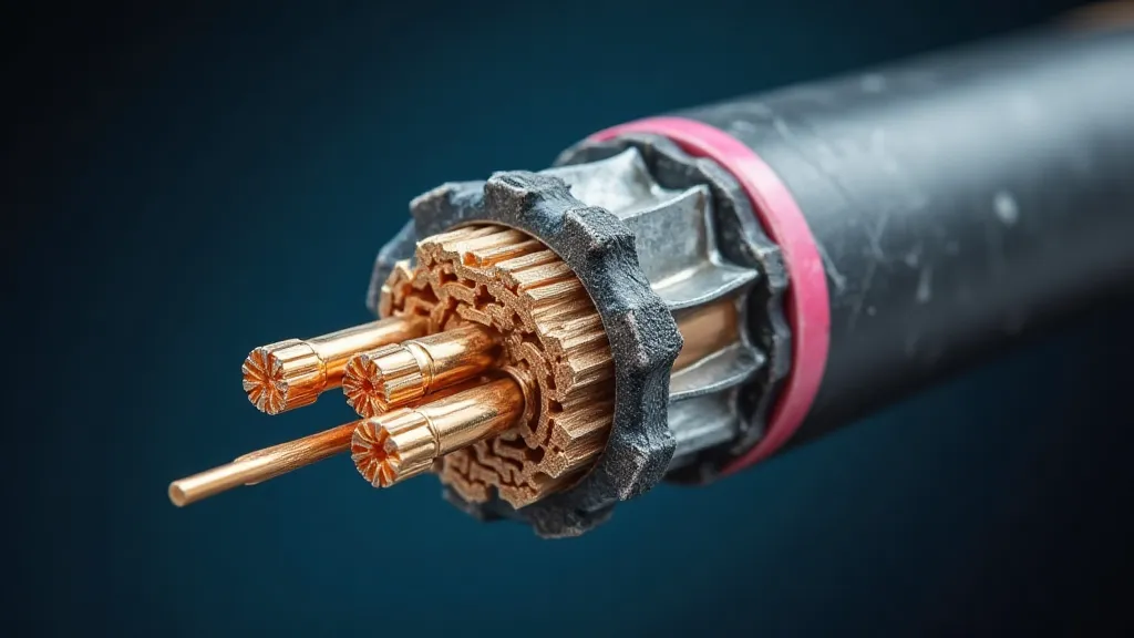
Simply put, a balun converts a balanced antenna system (like a dipole or a folded dipole) into an unbalanced feedline environment (typically coaxial cable). A balanced antenna has two equal and opposite conductors, while coaxial cable has a center conductor and a shield, creating an unbalanced configuration. Without a balun, these mismatched impedances can cause problems.
Why Do You Need a Balun? Understanding Common Mode Current
The biggest issue arises from common mode current. When an unbalanced feedline is connected directly to a balanced antenna, RF energy can leak from the outer shield of the coax, radiating unwanted signals. This radiated energy is not part of the intended signal and causes several issues:
- Reduced efficiency: The energy leaks, reducing the signal strength reaching the intended receiver.
- Interference: The stray radiation can interfere with other electronic devices and even broadcast on unauthorized frequencies.
- Increased antenna system noise: Common mode currents pick up noise from the environment.
- RFI (Radio Frequency Interference): Can cause problems with other electronics in your home or even your neighbors.
A balun acts as an isolation barrier, preventing this common mode current from flowing on the outer shield of the coax. It effectively suppresses the unwanted radiation and prevents noise from entering your receiver.
Types of Baluns
Baluns come in various forms, each with its own characteristics:
- Direct Connection Baluns: These are simple devices that connect the feedline directly to the antenna. They typically consist of a transformer with a 1:1 turns ratio.
- Current Baluns: Designed to suppress common mode currents.
- Voltage Baluns: Provide a more balanced voltage.
- Reversed Baluns: These are useful for compensating for antenna impedance mismatches.
For many common applications, a simple direct connection 1:1 balun is sufficient. We'll focus on building one of these.
Building a Simple 1:1 Balun
This project uses readily available materials and requires basic soldering skills.
Materials Required:
- Two Ferrite Cores (approx. 1" diameter, "snap-on" type are convenient)
- Two lengths of RG-58 or RG-8X coaxial cable (approximately 12" each)
- SO-239 connector (for connecting to the coax feedline)
- SPDT Switch (Single Pole Double Throw)
- Soldering Iron and Solder
- Wire strippers
- Small screws (for securing the switch)
- Enclosure (optional - to house the balun)
Construction Steps:
- Prepare the Coax: Strip the outer jacket and braid from both lengths of coaxial cable. Carefully expose about 1/2" of the center conductor and shield on each end.
- Wind the Cores: On each ferrite core, wind 8 turns of each coax's center conductor and 8 turns of each coax's shield. Make sure the windings are neat and tight.
- Connect the Switch: Connect the center conductor of one coax to one of the switch terminals. Connect the center conductor of the second coax to the other switch terminal. Connect both shields to the common terminal of the switch.
- Solder the SO-239 Connector: Solder the coax shield to the SO-239 connector’s outer shell. Solder the coax center conductor to the SO-239 center pin.
- Secure the Components: Secure the switch and SO-239 connector to a small piece of plastic or other insulating material.
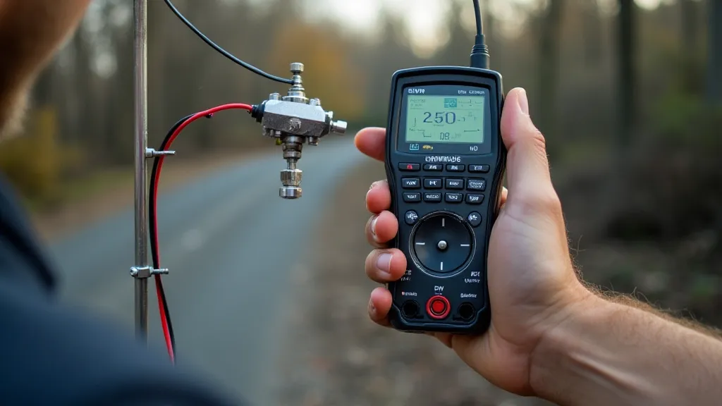
Testing Your Balun
While a sophisticated analyzer is ideal, a basic antenna analyzer or even a SWR meter can help verify the balun's functionality. You should observe a reduction in common mode currents, and ideally, a stable or improved SWR reading when the balun is connected to your antenna system.
By building and using a balun, you can significantly improve the performance and reduce the interference potential of your amateur radio antenna system. This relatively simple project provides a significant return on investment in terms of improved communication quality.