Constructing a J-Pole Antenna for VHF/UHF Bands
A J-pole antenna is a great alternative to a dipole for VHF and UHF bands. They are relatively easy to construct, omnidirectional, and offer good performance, making them a popular choice for amateur radio operators. This guide provides detailed instructions for building your own J-pole antenna.
What is a J-Pole Antenna?
The J-pole antenna is essentially a folded dipole that is fed at the junction of the two legs, creating a balanced feed point. This makes it easier to work with coaxial cable, a standard in ham radio. The “J” shape comes from the way the lower section is bent. Its performance is generally comparable to a dipole, but its design often makes it more rugged and less susceptible to environmental damage.
Materials Needed
- Two lengths of copper tubing or aluminum stock (typically 1.9" - 2" diameter, but can vary) - Lengths will be determined by frequency - see calculations below.
- Coaxial cable (RG-58 or RG-8X are common)
- SO-239 connector (for coaxial cable connection)
- Solder
- Flux
- Drill with appropriate drill bits
- Measuring tape
- Pipe cutter or hacksaw
- File or deburring tool
Calculating Dimensions
The dimensions of a J-pole antenna are frequency-dependent. Here's a simplified calculation for a 2-meter (144-148 MHz) J-pole. For other frequencies, you'll need to adjust these values:
- Length of Long Leg (L1): Approximately 54 inches (137 cm).
- Length of Short Leg (L2): Approximately 27 inches (68 cm).
- Distance from bottom of short leg to SO-239 connector: Around 4-6 inches (10-15cm). Experiment to find the best SWR.
These are starting points. Fine-tuning the length can be achieved through experimentation and using an SWR meter. There are also online J-pole calculators available that can provide more precise measurements for specific frequencies.
Construction Steps
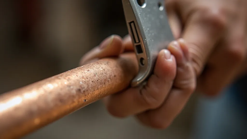
- Cut the Tubing: Using the calculated lengths, carefully cut the copper tubing or aluminum stock. Ensure accurate cuts for best performance.
- Deburr the Edges: File down any sharp edges or burrs from the cut ends. This is crucial for a clean solder joint.
- Assemble the Legs: Position the two lengths of tubing parallel to each other. The bottom ends of the legs will be separated a small distance (around 2-4 inches) to create the base of the J.
- Solder the Joint: Using flux and solder, securely join the two legs at their top ends. A strong, solid solder joint is vital for good signal transmission.
- Create the Base: Solder the bottom ends of the legs together, maintaining the desired separation. This creates the base of the J-pole.
- Attach the SO-239 Connector: Carefully solder the SO-239 connector to the point where the two legs join. This is the feed point. Ensure the connector is securely attached.
- Attach Coaxial Cable: Connect the coaxial cable to the SO-239 connector, ensuring a tight and secure connection.
Tuning and Testing
After construction, it's essential to tune the J-pole antenna. This is typically done using an SWR meter. The goal is to achieve an SWR as close to 1:1 as possible at the desired operating frequency.
- Initial SWR Check: Connect the SWR meter between the J-pole antenna and your radio.
- Adjust Length: If the SWR is high, make small adjustments to the lengths of the legs. Shortening the antenna generally lowers the frequency, and lengthening it raises it.
- Final Adjustment: Continue making small adjustments until you achieve a satisfactory SWR.
Important Considerations
- Safety: Always exercise caution when working with tools and electricity.
- Grounding: Proper grounding is essential for safety and to prevent interference.
- Environment: Consider the environment where the antenna will be installed. Protect it from weather and physical damage.